RF Dielectric Measurements & Moisture Measurement
Table of Contents
Understanding Dielectric Measurement
In the classical approach to the dielectric model, a material is made up of atoms. The atoms consist of a positive point charge at the center surrounded by a cloud of negative charge. The cloud of negative charge is bound to the positive point charge. The atoms are separated by enough distance such that they do not interact with one another. This is represented by the top left of figure 1, below. Note: Remember the model is not attempting to say anything about the structure of matter. It is only trying to describe the interaction between an electric field and matter.
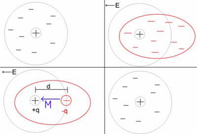
Electric field interaction with an atom under the classic dielectric model
In the presence of an electric field the charge cloud is distorted, as shown the top right of figure 1, above.
This can be reduced to a simple dipole using the superposition principle. A dipole is characterized by its dipole moment. This is a vector quantity and is shown as the blue arrow labeled M. It is the relationship between the electric field and the dipole moment that gives rise to the behavior of the dielectric. Note: The dipole moment is shown to be pointing in the same direction as the electric field. This isn’t always correct, but it is a major simplification, and it is suitable for many materials.
When the electric field is removed the atom returns to its original state.
Moisture Determination by Dielectric Measurement
Dielectric is the electrical property of a material relating to its behavior when subject to an electric field. Figure 1 illustrates the dielectric model of a material. Dielectric Constant or Relative Dielectric relates to the ease with which a material polarizes relative to a vacuum or, more practically, air. Table 1 shows the dielectric constants of a few common materials. Generally, solids exhibit relatively low dielectric constants. Exceptions include Titanium Dioxide (110) and many titanates. Water exhibits a very high dielectric; much higher than gypsum and most other solids. Thus, dielectric measurement can accurately resolve very low quantities of free water. Dielectric testing is particularly suited to determine moisture content in gypsum board and other gypsum products. The dielectric figure for gypsum itself varies. It is a function of crystal structure and, in the case of finished board, a function of density. For a particular product, these values are normally tightly controlled.
The dielectric constant for a salt solution is shown to demonstrate how little the dielectric constant is affected by ion concentration. Note that for liquids, the dielectric constant is given for a specific temperature. Temperature effect on solids is typically small, but on liquids can be significant. The internal temperature of a gypsum board after 1st zone drying should be very constant around 100°C, provided the board is not over-dried. Temperature compensation is therefore not required for gypsum board applications.
To illustrate how dielectric relates to moisture in a finished gypsum board, we will assume a typical gypsum dielectric value of:
Dry Gypsum Board Dielectric = 3.0
Gypsum Board containing 0.4% free moisture = (0.996 x 3.0) + (0.004 x 80) = 3.308
Gypsum Board containing 0.5% free moisture = (0.995 x 3.0) + (0.005 x 80) = 3.385
The ST-3300 Online RF Moisture Sensor is readily able to measure dielectric values with a resolution of 0.01, equivalent to approximately 0.013% moisture content in a gypsum board.
Resonant Frequency Dielectric Measurement
Numerous methods have been used to determine dielectric constant of a material. Radio frequency is often used for its ability to penetrate a material to a substantial depth and to be able to measure without contacting the material. Sensortech Systems developed and patented a specific method of dielectric determination using radio frequency. This is known as the resonant frequency technique.
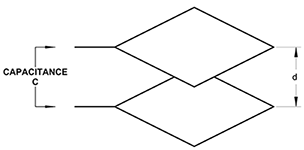
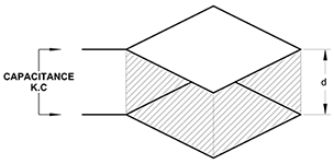
Parallel Plate Capacitor with Dielectric Medium
As previously stated, dielectric is a material property affecting the way it behaves in an electric field. A parallel plate capacitor is shown in figure 2(a). If the medium separating the plates is air or a vacuum, the capacitance is given by:
C = (εo ⋅ A) / d
Where:
εo = permitivitty of free space = 8.854 x 10⁻¹²
A = Area of plate
d = separation distance of plates
When a dielectric medium separates the plates as in figure 2(b), capacitance becomes:
C = (εo ⋅ εr ⋅ A) / d
Where:
εr = dielectric constant
Thus, capacitance is directly proportional to the dielectric constant of the material in the electric field.
C = K ⋅ εr
Parallel plate capacitance sensors are rarely used for industrial applications; single-sided sensors being preferred.
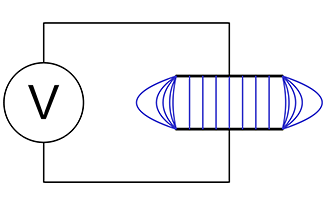
Parallel plate capacitor showing flux lines
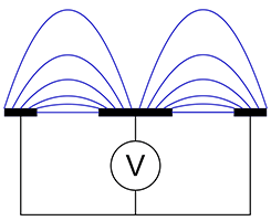
Planar sensor antenna showing flux lines
Figure 3(a) is schematic representation of a parallel plate capacitor showing uniform electric flux lines except at the edges where fringing occurs. The fringe field is generally undesirable in a capacitor, but in a single-sided capacitance sensor, it is the only useful field.
Figure 3(b) is a cross-sectional view of a planar sensor, most frequently used for gypsum board applications. A central element propagates an electric field to the grounded side plates. A small proportion of the field is directly between electrodes, but most is the fringe field used to penetrate the board. Figure 4 shows a photograph of a planar sensor.
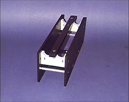
Example of an open frame planar sensor antenna
Electrically, the sensor, sometimes termed antenna, is simply a capacitor. The electrical analogy of the gypsum product is itself a capacitance with parallel resistance. The resistance or conductance represents the ionic conductance or dielectric loss in the board.
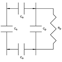
Electrical schematic of product coupling
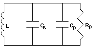
Electrical schematic of equivalent resonant circuit
Figure 5(a) shows the electrical schematic of the product coupled to the capacitive sensor. Air gap capacitance (Ca) couples the product (Cp) to the sensor (Cs) and must, therefore, be kept constant. Mounting the sensor between conveyor rollers, spaced perhaps 6mm below the plane of the rollers, ensures a constant coupling capacitance, provided rollers are reasonably true. The capacitance’s may be combined as one (CT) which, while mathematically incorrect, may simplistically be represented as CT = Cs + Cp.
Figure 5(b) illustrates the resonant network formed by sensor capacitance in parallel with product capacitance also in parallel with inductor (L). This network has a unique resonant frequency at which inductive reactance cancels capacitive reactance and network impedance is at a maximum. Impedance at resonance is actually resistance (Rp).
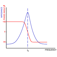
Frequency, phase, and impedance relationships of resonant network
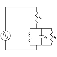
Electrical schematic example of a resonant circuit
The resonant network is driven from a suitable RF signal through a pure fixed resistor (Ro) as shown in figure 6(a). As frequency increases, the network is first of all inductive with a leading phase angle. At resonance all reactive components cancel and the circuit is purely resistive. At resonance, the signal amplitude across the resonant network is a function of only Ro, Rp and amplitude of the driving signal. Ro and Rp behave as a simple potential divider.
Using a precision phase lock loop to adjust signal frequency to maintain zero phase angle across resistor Ro ensures the network is always at resonance.
Resonant frequency is defined as:
fo = 1 / [2π√(L x CT)]
The ST-3300 measures this frequency to a 32-bit resolution. A proprietary measurement algorithm combines sensor frequency with two reference frequencies to produce a dielectric value that is essentially independent of ambient temperatures and component aging.
The resulting raw dielectric can be seen to be a function of sensor capacitance (with product) and precision reference capacitors. Inductance and stray capacitance are eliminated.
Moisture is directly proportional to the raw dielectric.
Given a linear relationship, the instrument can now be calibrated from analytical data to fit a linear function of the form:
Moisture = a x D + b
Since capacitance CT is a composite of both the sensor and the product, it is necessary to remove the influence of sensor capacitance. This is achieved by measuring sensor capacitance when no product is present (Dz) and subtracting this from future measurement in a similar way to taring a weigh scale. This action is termed ‘Pre-zero’ and should be performed periodically to compensate for antenna changes and product build-up on the antenna.
Related Blog Posts


